4.7 Setup Region of Interest and Custom Blocks
Fine-tune Region of Interest
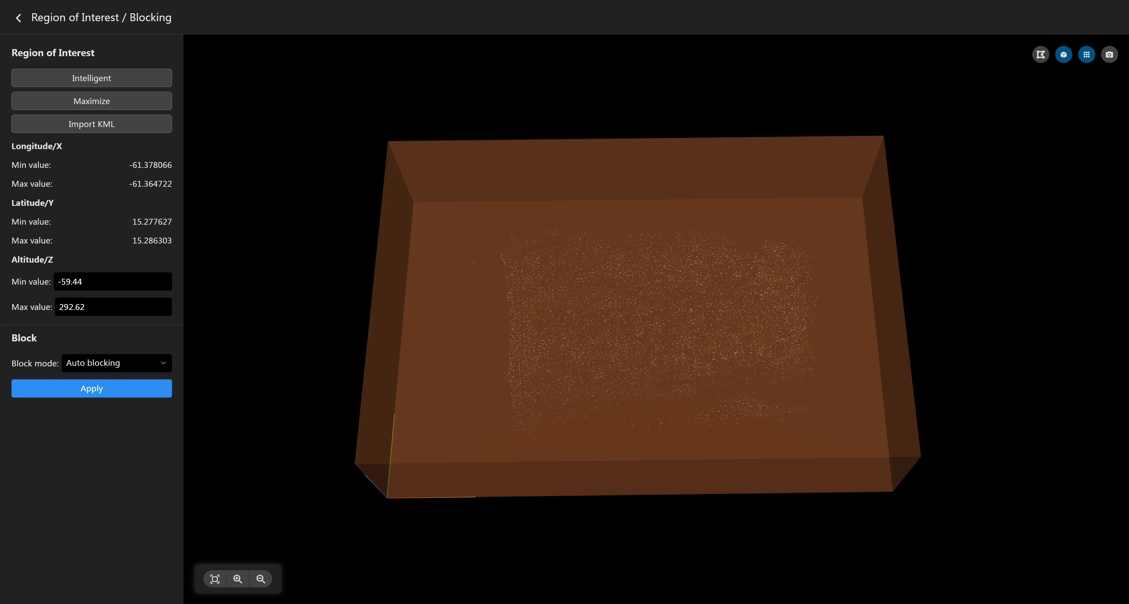
In addition to presetting the region of interest, the software also supports setting a more accurate region of interest based on the aerial triangulation results after completion. Click the "Set Region of Interest/Blocks" button to enter the ROI and custom block settings page.

- Switch Region of Interest If the region of interest was not set before aerial triangulation, the maximized region of interest will be used by default to ensure all point clouds are included in the reconstruction range. You can switch between different regions of interest through the left panel. The "Smart" region of interest is intelligently calculated by the software based on the point cloud distribution. You can also import a KML file to set a custom region of interest.
- Region of Interest Editing
There are some toggle buttons in the upper right corner of the region of interest map. Click
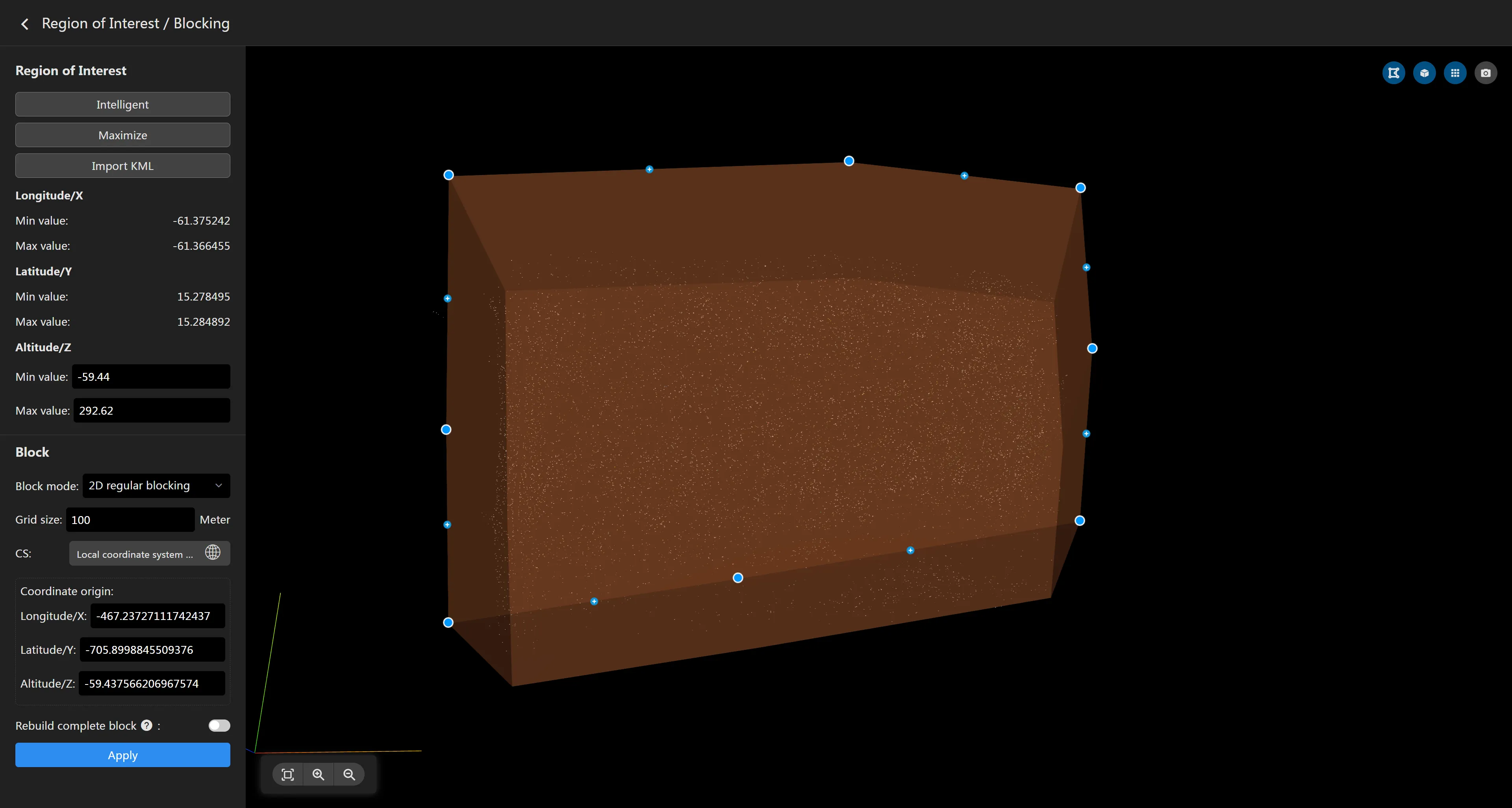
to enter the region of interest editing mode. The map will display the vertices of the region of interest boundary. Click a vertex to drag its position to adjust the range of the region of interest. Click the "+" button in the middle to add a vertex. Move the mouse to a node and right-click to delete the node. The left panel allows you to adjust the minimum and maximum height of the region of interest.

- Saving Region of Interest
Settings are automatically saved by default. After setting, click the arrow
in the upper left corner of the page to return to the task page.
Custom Blocks
By default, the software automatically divides blocks based on the memory size of the computing device. If there are no special requirements, you do not need to set custom blocks.
- Set Block Coordinate System The default block coordinate system is a LocalENU coordinate system with the origin at the lower right corner of the maximized region of interest. If you need to customize the block coordinate system, you can select the coordinate system and coordinate origin in the block settings panel. This coordinate system only serves as the origin for blocking and does not affect the coordinate system of the reconstruction results. If you need to set the coordinate system for the output results, please do so in the reconstruction results parameter panel.
- Block Mode The software supports 3 block modes: 2D Regular Blocking: Ignores the height information of the reconstruction area and performs regular blocking only in the XY plane according to the specified grid and coordinate system. 3D Regular Blocking: Considers the height of the reconstruction area and performs regular blocking in the X, Y, and Z directions according to the specified grid and coordinate system. Block by Memory: Performs adaptive blocking by specifying the maximum memory occupied by each block.
- Reconstruct Complete Blocks
If a block is located exactly on the boundary of the region of interest, it may cause this block to be cut by the region of interest, resulting in only a partial reconstruction. If you want blocks on the boundary of the region of interest to be reconstructed completely, you can turn on the
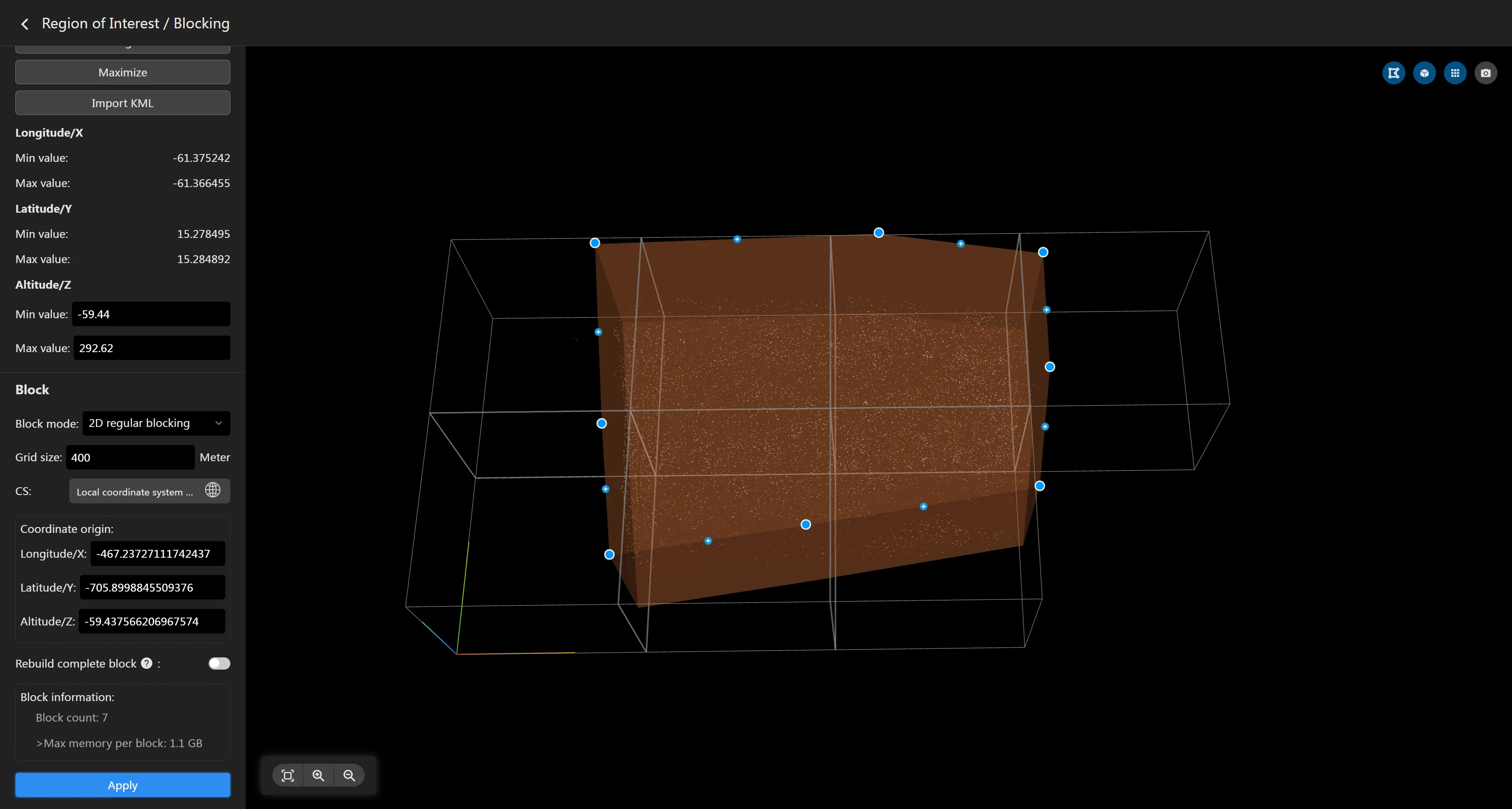
**Reconstruct Complete Blocks**switch. In large-area mapping tasks, the reconstruction area is usually divided into sub-tasks. For blocks on the cutting boundary, turning on**Reconstruct Complete Blocks**can avoid the problem of incomplete boundary blocks after merging. To achieve good results, ensure sufficient image overlap for boundary blocks. - Save Block Parameters After setting the block information, click the "Apply" button. The interface will display specific block information and the maximum memory occupied by a single block. Please note that the maximum memory cannot exceed the maximum available memory of the computing device, otherwise it may lead to block reconstruction failure.

If the block grid does not meet the requirements, you can adjust the parameters and click "Apply" again. After setting, click return to automatically save the block information.