4.1 Quick Reconstruction
Create Task
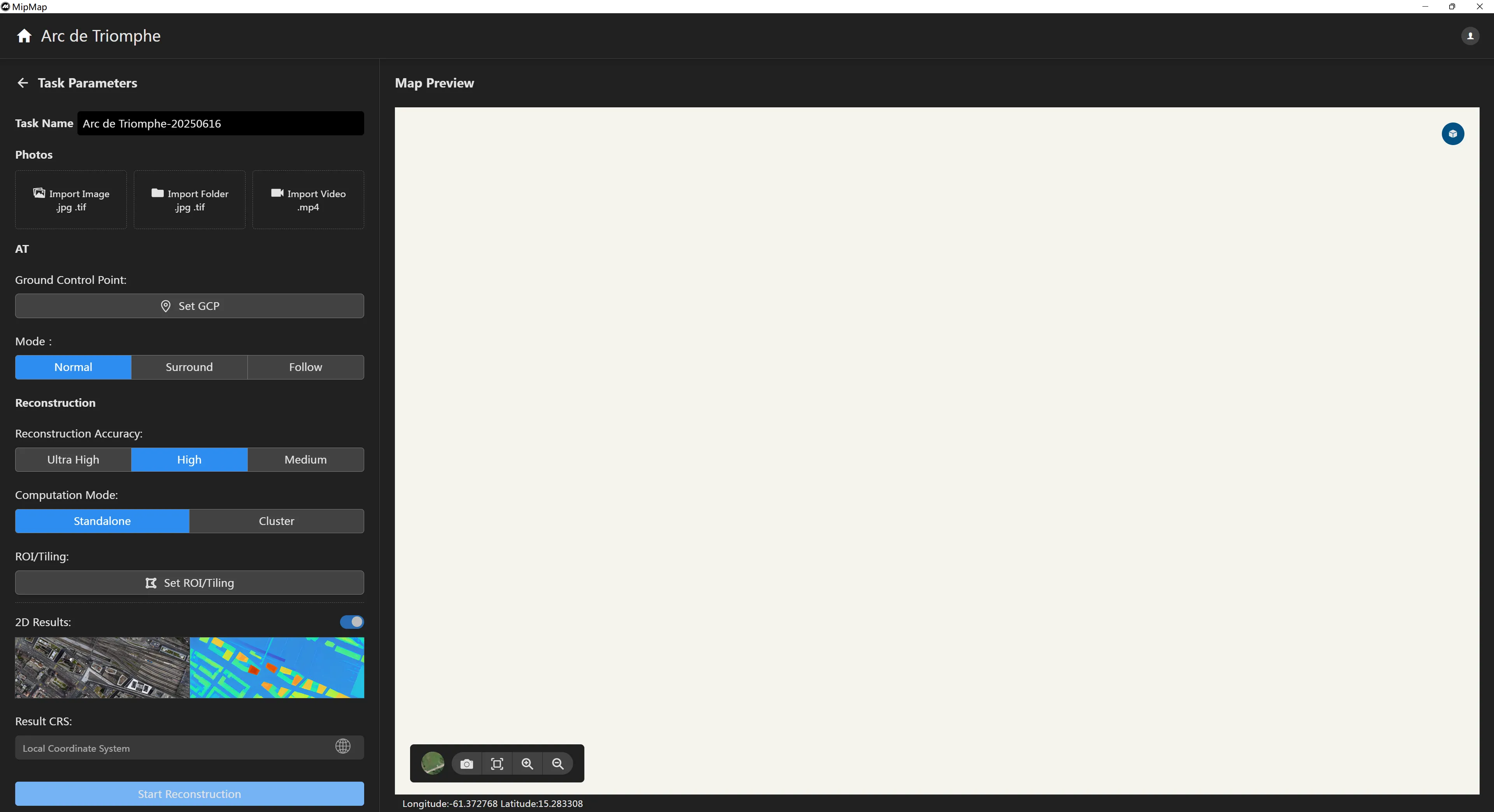
On the [Project List] page, click the button or, within an existing project, click the
button to automatically go to the task creation page.
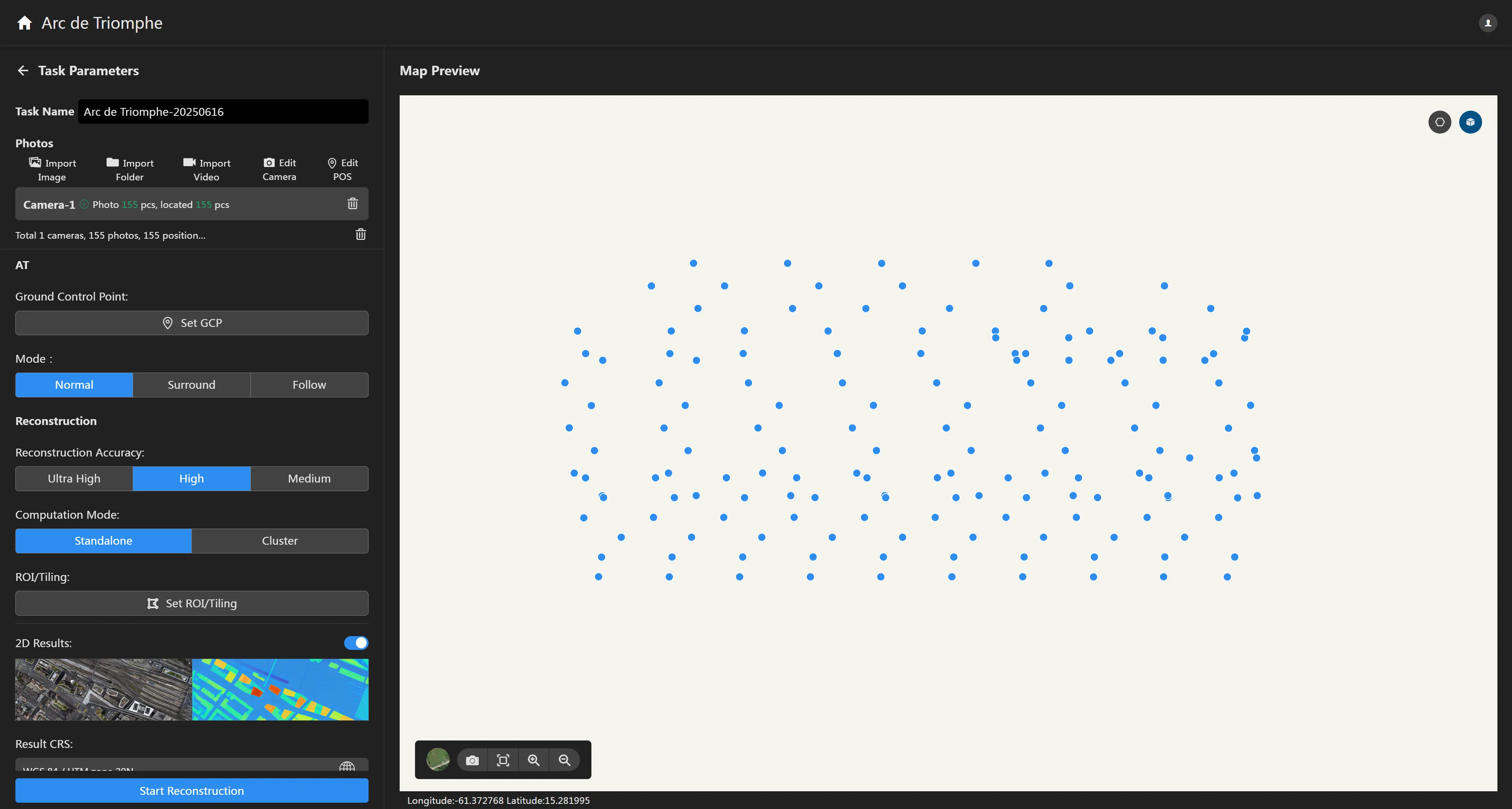
Upload Photos
Click the "Import Images" or "Import Folder" button, select the photos you want to reconstruct, and click "OK". The software will automatically read the photos and obtain the attribute information from them.
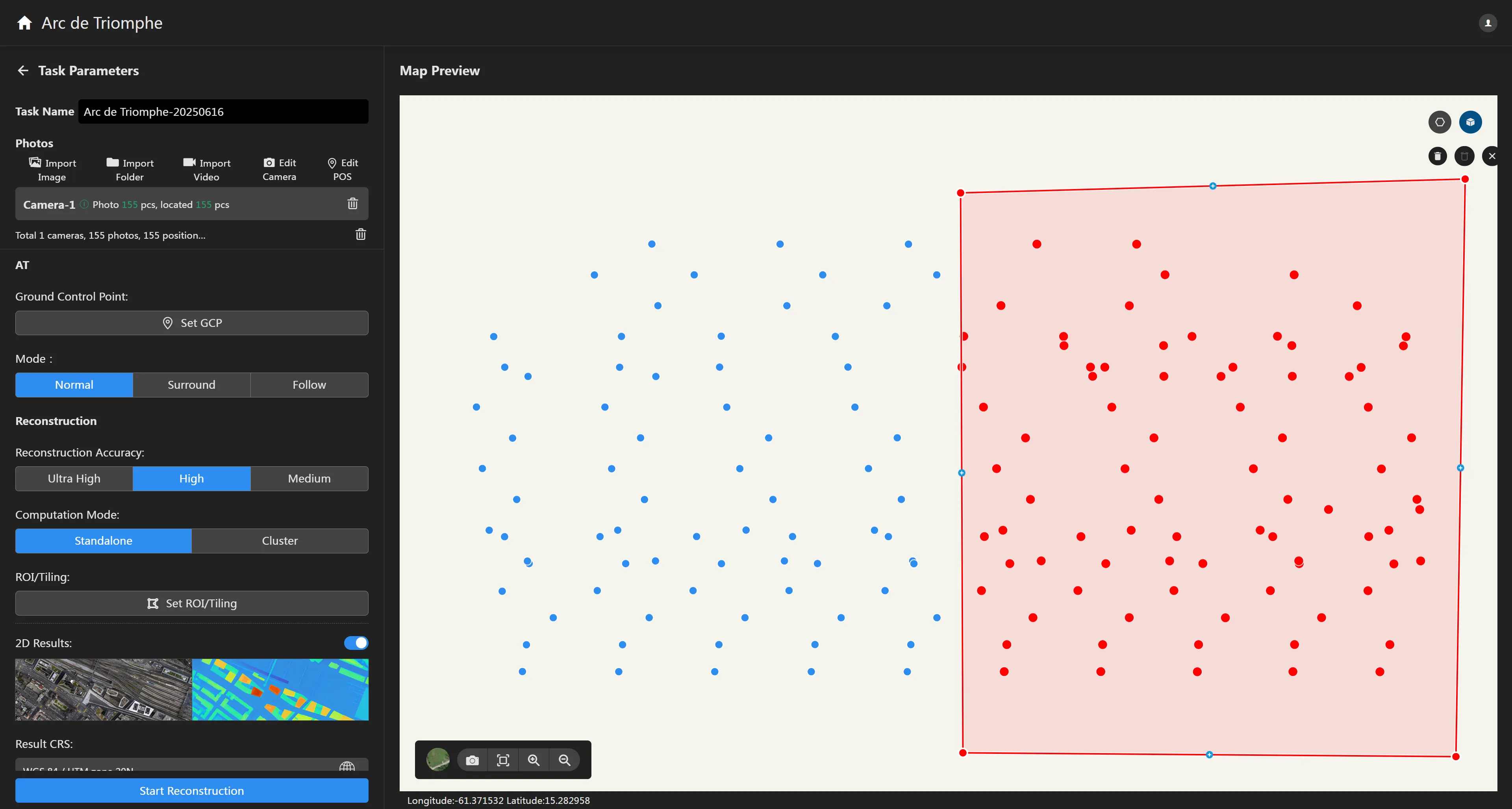
Click the button on the map preview interface to draw a polygonal area. You can choose to delete image data inside or outside the area. Deleted images will not participate in the reconstruction process.
Click the "Import Video" button, select the video you want to reconstruct, and the video frame extraction interface will automatically appear. After setting the frame extraction parameters, click "OK", and the software will automatically extract frames and read the photos. If the video file directory contains an srt file with the same name that includes video POS information, automatic extraction of video pose is supported.
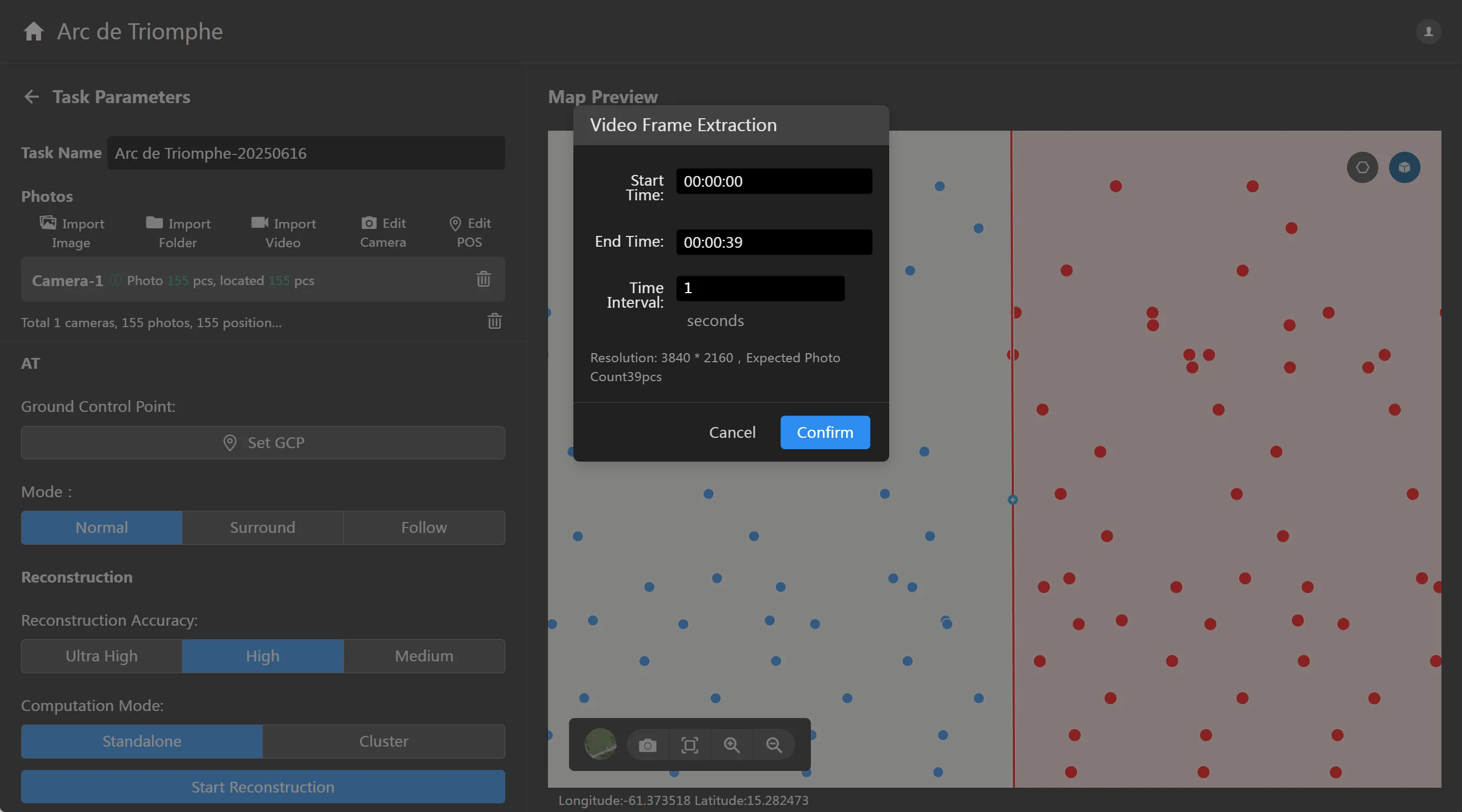
Set Reconstruction Parameters
After importing photos, the software will automatically set default reconstruction parameters based on the parsed photo data. You can also manually modify the reconstruction parameters you want.
- Set Ground Control Points (GCPs): If the dataset has control points, you can import them and perform GCP marking to improve aerial triangulation accuracy. GCPs are generally set after aerial triangulation is complete.
- Aerial Triangulation Mode:
- Reconstruction Accuracy: The higher the reconstruction accuracy, the higher the resolution of the reconstructed results, but it will consume more time. Conversely, the lower the accuracy, the faster the reconstruction speed. The difference between high, medium, and low reconstruction accuracy lies in the resampling resolution relative to the original image: High has the same resolution as the original image, Medium is resampled at a 2x interval from the original image (i.e., both length and width are 1/2 of the original image), and Low is resampled at a 4x interval from the original image (i.e., both length and width are 1/4 of the original image). For example: if the original image's length × width is 6000 × 4000, the high-accuracy reconstructed image's length × width will be 6000 × 4000, the medium-accuracy reconstructed image's length × width will be 3000 × 2000, and the low-accuracy reconstructed image's length × width will be 1500 × 1000.
- Computation Mode: You can choose between single-machine computation or cluster computation. Cluster computation requires that the cluster service has been deployed and you have authorization for cluster computation.
- Set Region of Interest (ROI)/Blocks: You can set the desired reconstruction area and blocking method according to your needs.
- 2D Results: 2D results mainly include Digital Orthophoto Maps (DOM) and Digital Surface Models (DSM). Disabling this option will not output 2D image results. Note that if the imported photos do not contain location information, 2D results cannot be reconstructed.
- 2D Results Advanced Settings: 2D results support setting pyramid output, tiled output, and resolution settings. Tiled output allows setting the tile side length, and resolution can be set to automatic or manual input of 2D result GSD.
- 2D Results Coordinate System: The default output coordinate system is an arbitrary coordinate system, usually a local coordinate system. If you need to customize the coordinate system, you can click
to select the coordinate system you want to output.
- 3D Results: 3D results mainly include 3D models and point clouds. Disabling this option will not output 3D results. In this interface, users can select the output format for models and point clouds according to specific needs, including B3DM\OSGB\OBJ\PLY format models and PNTS\OSGB\LAS\PLY format point clouds.
- 3D Results Advanced Settings: 3D results support setting model simplification rate and deleting floating objects. The model simplification rate defaults to 100%, outputting the complete model.
- 3D Results Coordinate System: Similar to the 2D results coordinate system, it defaults to an arbitrary coordinate system. You can click
to set it to a custom coordinate system.
- Elevation Coordinate System: The coordinate system selection page allows choosing an elevation system. Currently, it supports geodetic height, 1985 National Vertical Datum, and custom elevation systems. Custom elevation systems are added by importing tif format geoid undulation files.
Start Reconstruction
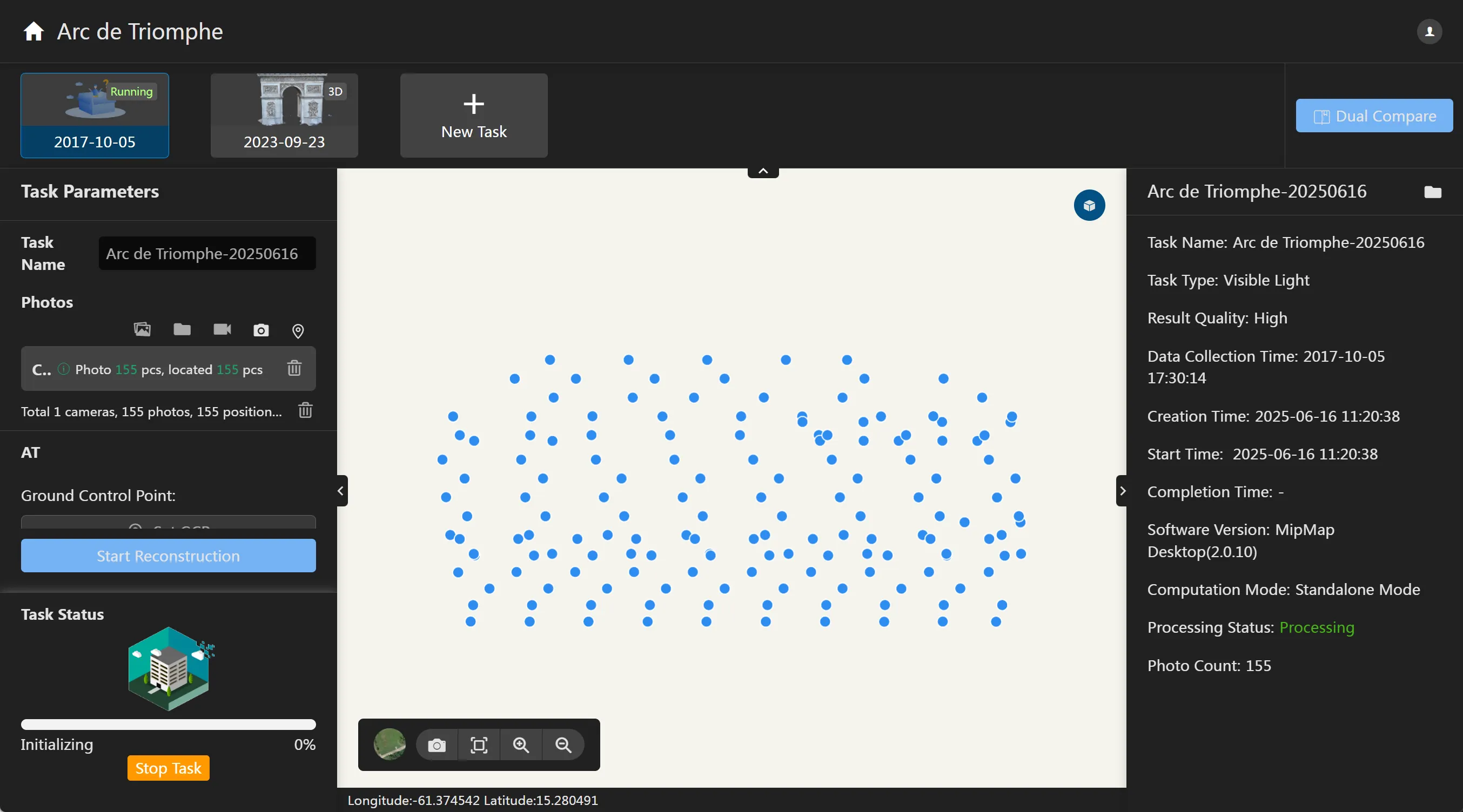
Click the "Start Reconstruction" button, and the software will automatically enter the reconstruction process. In the lower-left corner, you can view the current task execution stage and progress. After reconstruction is complete, the reconstructed results will be automatically displayed.
